No products in the basket.

Selecting the right pump for a plumbing, heating or water management application involves more than simply looking at the motor power or the size of the connections. One of the most important tools for choosing the correct pump is the manufacturer’s pump performance chart, commonly known as a pump curve.
Pump curves provide valuable information about how a pump will perform under different operating conditions. They show how much water a pump can move, how much pressure or head it can generate, how efficiently it operates and how much power it consumes.
However, for anyone unfamiliar with them, pump charts can initially look complicated.
In this guide, we explain how to read pump performance curves, what the different lines and measurements mean, and how to use this information when selecting pumps for real-world applications. We'll also look at several common pump types and explain how their performance characteristics differ.
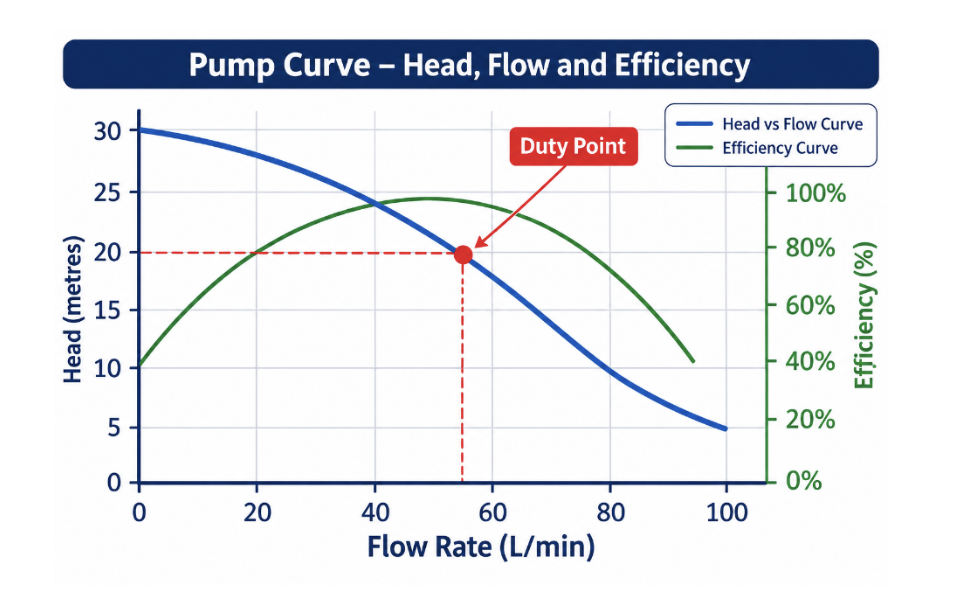
The important thing to understand is that a pump does not deliver its maximum flow rate and maximum head simultaneously. Its actual performance is determined by the relationship between the pump and the system it is connected to.
2. Understanding Flow Rate
Flow rate tells you how much liquid a pump can move over a specific period.
It is particularly important when selecting pumps for applications such as:
- Domestic water supply and boosting.
- Central heating circulation.
- Irrigation systems.
- Tank filling and emptying.
- Drainage and wastewater removal.
- Industrial water transfer.
3. Understanding Pump Head
Head is one of the most important measurements on a pump performance chart.
It describes the energy the pump adds to the liquid, expressed as the equivalent height of a column of that liquid in metres.
Although head is often associated with how high a pump can lift water, it also accounts for the resistance created by pipework, fittings, valves and other components in the system.
For water, a useful approximate conversion is:
- 1 metre of head = 0.098 bar.
- 10 metres of head = 0.98 bar.
- 20 metres of head = 1.96 bar.
- 30 metres of head = 2.94 bar.
This is why a pump advertised as having a maximum head of 30 metres does not necessarily mean it can deliver water 30 metres vertically while maintaining a useful flow rate.
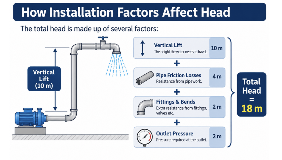
The actual head required by an installation includes several factors:
- Vertical height the water needs to travel.
- Friction losses through the pipework.
- Resistance from bends, tees and fittings.
- Pressure requirements at the outlet.
- Differences between suction and discharge conditions.
For example, imagine a pump supplying water to a property where the highest outlet is 8 metres above the pump. If pipework and fittings account for another 4 metres of head loss, and the outlet needs an additional 10 metres of pressure head, the system requires approximately 22 metres of head.
The pump must be capable of delivering the required flow rate at that head, not simply achieve a maximum head figure of 22 metres.
4. How to Read a Pump Curve
Once you understand flow rate and head, reading the main performance curve becomes much easier.
1. Start by identifying the flow rate required by your installation along the horizontal axis.
2. Move vertically upwards until you reach the pump's head curve.
3. Move horizontally towards the vertical axis to establish the available head.
4. Pump's performance at that particular flow rate.
E.G. Selecting a pump for a water supply system
Imagine a small commercial installation requires:
- Flow rate: 40 L/min.
- Required head: 20 metres.
On the manufacturer's pump chart, locate 40 L/min along the bottom axis and move upwards to the head curve. If the curve shows that the pump can deliver 24 metres of head at 40 L/min, it may be suitable, provided the remaining installation requirements are also satisfied. If the pump only produces 15 metres of head at that flow rate, it will not meet the required duty. The important point is to look at the performance curve at the required flow rate, rather than selecting a pump based on its advertised maximum head or maximum flow figure.
6. Understanding the Duty Point
The duty point is the combination of flow rate and head that the pump needs to achieve for the installation to operate correctly. For example, a system might require:
- 2.5 m³/h flow rate.
- 18 metres of head.
This combination is the required duty point. The pump must be capable of achieving both figures simultaneously. A pump might have a maximum flow rate of 5 m³/h and a maximum head of 30 metres, but these maximum values will normally occur at different points on its performance curve. Therefore, simply comparing maximum flow and maximum head figures can lead to an incorrect pump selection.
7. Different Types of Pumps and Their Performance Curves
Centrifugal Pumps
They use a rotating impeller to transfer energy to the liquid, creating flow and pressure. Their performance curves generally show decreasing head as flow increases. Common applications include:
- Water transfer.
- Domestic and commercial water supply.
- Heating and cooling systems.
- Irrigation.
- Industrial circulation.
- General water distribution.
When selecting a centrifugal pump, the head-flow curve is particularly important because it shows the relationship between the required flow rate and the available head.
Circulator Pumps
They are designed to keep water moving around a closed or recirculating pipework system. Unlike a pump used to transfer water between two tanks, a heating circulator is primarily overcoming friction and resistance within the system. Their performance charts often include several curves representing different operating speeds or control settings. Modern electronically controlled circulator pumps may also feature variable-speed operation, automatically adjusting their output to match system demand. For example, a heating system with thermostatic radiator valves may require less circulation as individual rooms reach their target temperatures. A variable-speed circulator can reduce its output as resistance changes, helping to reduce electricity consumption and unnecessary noise.
Booster Pumps
Booster pumps are designed to increase water pressure and maintain adequate flow throughout a building or installation. They are commonly used in:
- Domestic properties with low mains pressure.
- Commercial buildings.
- Multi-storey properties.
- Irrigation systems.
- Water distribution networks.
Booster pump charts help establish whether the pump can deliver the required flow while maintaining sufficient outlet pressure. For example, a property might require 30 L/min at an additional 2 bar of pressure. The pump curve must show that the selected model can achieve this combination. Some booster systems use pressure sensors, flow switches or variable-speed drives to maintain a consistent outlet pressure as water demand changes.
Submersible Pumps
Submersible pumps operate while fully immersed in the liquid they are designed to pump. They are frequently used for drainage, wastewater, sewage, groundwater removal and water transfer. Their performance curves are particularly useful when calculating how quickly water can be removed from a flooded area, sump or tank. For example, a drainage installation may require a pump to move 10 m³/h against a total head of 6 metres. It is important to remember that submersible pumps are not all designed for the same liquids. Clean-water, drainage and sewage pumps can have very different impeller designs and solids-handling capabilities.
Multistage Pumps
Multistage pumps use multiple impellers arranged in series to generate higher pressures than a conventional single-stage pump. They are commonly found in:
- High-pressure water boosting.
- Commercial buildings.
- Boiler feed applications.
- Reverse osmosis systems.
- Industrial water treatment.
- Pressure washing installations.
Their performance curves generally show the ability to maintain useful flow rates at considerably higher heads. For example, a multistage pump may be selected where water needs to be supplied to a building several floors above the plant room while maintaining adequate pressure at the outlets. When comparing multistage pump charts, check the number of stages, motor speed and available pump configuration, as these all affect performance.
9. Common Mistakes When Reading Pump Charts
- Choosing a pump based on maximum head alone
Maximum head is normally achieved at or close to zero flow on a conventional centrifugal pump. It does not represent the head available when delivering a useful volume of water.
- Choosing a pump based on maximum flow alone
Maximum flow is generally achieved at very low system resistance. Once connected to real pipework, the actual flow will be lower.
- Ignoring pipework resistance
Long pipe runs, small pipe diameters, bends, valves and fittings all create resistance. These losses must be included when calculating the required pump head.
- Ignoring efficiency
A pump that meets the required duty point but operates well away from its Best Efficiency Point may consume more electricity than necessary.
- Selecting the wrong pump type
A heating circulator, drainage pump and high-pressure booster pump are designed for different applications. Their performance curves cannot simply be compared without considering their intended purpose.
- Ignoring the liquid being pumped
A standard water performance chart may not accurately represent performance with hot, viscous or chemically aggressive liquids. Solids content and fluid properties can also affect pump selection.
We understand how important it is to choose the correct equipment for the job. If you need help finding a suitable pump, contact our sales team at sales@colglo.co.uk or call 01244 288000